


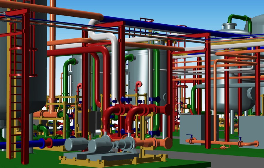
Modern industrial facilities have become increasingly complex, requiring thousands of interconnected components to function safely and efficiently. Process plants in industries such as oil and gas, chemical manufacturing, mining, power generation, water treatment, pharmaceuticals, food processing, and renewable energy contain extensive networks of piping, structural steel, pressure vessels, storage tanks, pumps, compressors, heat exchangers, and instrumentation. Successfully designing and constructing these facilities demands precise engineering coordination and comprehensive digital modeling.
Plant 3D modeling has transformed the way engineering teams develop industrial projects. Instead of relying on traditional two-dimensional drawings, engineers create intelligent three-dimensional models that accurately represent every component within the facility. These models integrate piping layouts, equipment placement, structural systems, cable trays, supports, valves, and instruments into a coordinated digital environment.
When combined with professional piping design, automatic isometric drawing generation, and spool fabrication drawings, Plant 3D technology significantly improves engineering accuracy, reduces design conflicts, accelerates fabrication, and supports efficient project execution. Every stakeholder, including designers, fabricators, contractors, inspectors, and project managers, benefits from consistent and reliable project information throughout the project lifecycle.
This article explains the engineering workflow and outlines the key steps that demonstrate how Plant 3D modeling, piping design, isometric generation, and spool drawings streamline industrial project delivery.
What Is Plant 3D Modeling?
Plant 3D modeling is the process of creating an intelligent three-dimensional digital representation of an industrial facility.
The model typically includes:
- Process equipment
- Piping systems
- Structural steel
- Pipe supports
- Pressure vessels
- Storage tanks
- Valves
- Instruments
- Cable trays
- Access platforms
Each component contains engineering information used throughout the project.
What Is Piping Design?
Piping design involves developing safe, efficient, and code-compliant piping systems that transport liquids, gases, steam, and other process fluids.
Piping engineers determine:
- Pipe routing
- Pipe sizes
- Materials
- Valve locations
- Support locations
- Expansion provisions
- Equipment connections
- Maintenance access
Proper piping design supports long-term plant reliability.
What Are Isometric Drawings?
Piping isometric drawings are detailed engineering documents that show individual piping lines in a three-dimensional format.
Typical information includes:
- Pipe dimensions
- Weld locations
- Component identification
- Pipe fittings
- Valves
- Supports
- Material specifications
- Bill of materials
Fabrication shops rely heavily on isometric drawings.
What Are Spool Drawings?
Spool drawings divide large piping systems into manageable fabrication sections.
Each spool drawing typically contains:
- Pipe lengths
- Weld joints
- Flanges
- Fittings
- Dimensions
- Material lists
- Identification numbers
These drawings simplify fabrication and installation.
Industries That Use Plant 3D
Plant 3D technology is widely used across numerous industries.
Examples include:
- Oil and gas
- Chemical processing
- Mining
- Power generation
- Water treatment
- Pharmaceutical manufacturing
- Food processing
- Pulp and paper
- Renewable energy
- Industrial manufacturing
Benefits of Digital Plant Models
Three-dimensional plant models improve engineering coordination.
Advantages include:
- Better visualization
- Improved communication
- Faster design reviews
- Reduced design conflicts
- Improved accuracy
- Easier project coordination
Digital models support informed engineering decisions.
Engineering Data Integration
Modern Plant 3D software stores engineering information within every model component.
Data may include:
- Material specifications
- Pressure ratings
- Line numbers
- Equipment tags
- Valve specifications
- Pipe schedules
- Component dimensions
Integrated data improves project consistency.
Clash Detection
One of the greatest advantages of Plant 3D is clash detection.
The software identifies conflicts between:
- Piping
- Structural steel
- Equipment
- Cable trays
- Ductwork
- Maintenance access areas
Resolving clashes early reduces construction delays.
Automatic Documentation
Plant 3D automatically generates numerous project documents.
These include:
- Isometric drawings
- Material takeoffs
- Equipment lists
- Pipe schedules
- Bills of materials
- Fabrication reports
Automation reduces manual drafting work.
Fabrication Support
Accurate engineering drawings improve fabrication quality.
Fabricators receive:
- Clear dimensions
- Weld information
- Material specifications
- Component identification
- Assembly details
Better drawings reduce fabrication errors.
Construction Coordination
Digital engineering supports efficient construction planning. Discover practical project delivery methods through Plant 3D Modeling, Piping Design, Isometric & Spool Generation.
Project teams can coordinate:
- Installation sequencing
- Material deliveries
- Equipment access
- Crane operations
- Structural erection
- Pipe installation
Proper coordination minimizes delays.
Quality Assurance
Plant 3D improves engineering quality through standardized documentation and model consistency.
Quality activities include:
- Design reviews
- Model verification
- Engineering approvals
- Revision control
- Documentation management
Quality assurance improves project reliability.
Steps That Streamline Project Delivery
Step 1: Gather Complete Project Requirements
Every successful project begins by collecting accurate engineering information. Engineers define process requirements, equipment specifications, operating conditions, piping classes, design codes, client standards, and project objectives before developing the digital model.
Step 2: Develop the Initial Plant Layout
The overall facility layout is established by positioning major equipment such as pressure vessels, storage tanks, pumps, compressors, heat exchangers, and process units. Proper equipment placement improves accessibility, safety, maintenance, and future expansion opportunities.
Step 3: Build the Intelligent Plant 3D Model
Engineers create a detailed three-dimensional model that incorporates all major plant components. Every object contains engineering data that supports design coordination, material management, fabrication, and construction.
Step 4: Design the Piping System
Piping engineers develop pipe routing that satisfies process requirements while considering pressure losses, thermal expansion, structural support, maintenance access, drainage, and applicable engineering codes. Proper routing improves operational efficiency and equipment reliability.
Step 5: Coordinate Multiple Engineering Disciplines
Mechanical, piping, structural, electrical, instrumentation, and civil engineering teams work together within the digital model. Coordinated engineering reduces conflicts and improves overall project quality.
Step 6: Perform Clash Detection
The completed model is reviewed for physical conflicts between piping, equipment, structural members, cable trays, platforms, and access routes. Early clash resolution eliminates many costly construction changes.
Step 7: Verify Engineering Accuracy
Engineers review pipe specifications, support locations, equipment connections, nozzle orientations, elevations, dimensions, and clearances to ensure that every component complies with project requirements before documentation is released.
Step 8: Generate Isometric Drawings
After the piping model is finalized, the software automatically generates piping isometric drawings. These documents provide fabricators and installers with accurate dimensions, weld locations, component identification, and material information.
Step 9: Produce Spool Drawings for Fabrication
Large piping systems are divided into fabrication spools that simplify manufacturing, transportation, quality inspection, and field installation. Spool drawings improve workshop productivity and reduce assembly errors.
Step 10: Prepare Bills of Materials
The intelligent model automatically generates material lists that include pipes, fittings, valves, flanges, gaskets, supports, bolts, and other components. Accurate bills of materials improve procurement and inventory management.
Step 11: Support Construction and Installation
Construction teams use the three-dimensional model, isometric drawings, and spool documentation to plan installation activities, coordinate equipment deliveries, verify dimensions, and improve field productivity throughout the project.
Step 12: Maintain the Digital Model Throughout the Project Lifecycle
The Plant 3D model remains valuable after construction is complete. It supports commissioning, maintenance planning, equipment replacement, future plant modifications, inspections, and long-term asset management.
Engineering Considerations
Successful Plant 3D projects require attention to several important engineering factors.
These include:
- Compliance with applicable design codes
- Accurate equipment data
- Consistent piping specifications
- Proper support design
- Thermal expansion evaluation
- Stress analysis coordination
- Material compatibility
- Maintenance accessibility
- Safety clearances
- Future plant expansion
Addressing these considerations improves overall project performance.
Benefits of Plant 3D Modeling, Piping Design, Isometric and Spool Generation
Professional digital engineering provides numerous advantages.
These benefits include:
- Improved engineering accuracy
- Faster project execution
- Better multidisciplinary coordination
- Reduced design conflicts
- Improved visualization
- Higher drawing quality
- Faster isometric generation
- Simplified spool fabrication
- Better material tracking
- Improved procurement planning
- Reduced fabrication errors
- Faster field installation
- Lower construction costs
- Better quality control
- Improved maintenance planning
- Enhanced project documentation
- Reduced project risk
- Increased operational reliability
- Better lifecycle asset management
- Greater client confidence
Best Practices for Successful Digital Plant Engineering
Professional engineering teams generally follow several best practices.
These include:
- Establish project standards before modeling begins.
- Maintain consistent component libraries and specifications.
- Verify equipment dimensions before routing piping.
- Perform regular model reviews throughout the project.
- Coordinate all engineering disciplines within the shared model.
- Conduct clash detection before issuing construction drawings.
- Validate piping supports and stress analysis results.
- Keep engineering documentation synchronized with model revisions.
- Review automatically generated isometric drawings before release.
- Maintain accurate revision control throughout the project lifecycle.
Future Trends in Plant 3D Engineering
Digital engineering technologies continue to transform industrial project delivery.
Emerging developments include:
- Artificial intelligence-assisted piping design
- Cloud-based collaborative engineering platforms
- Digital twin integration
- Automated clash resolution
- Real-time project monitoring
- Machine learning for design optimization
- Virtual reality model reviews
- Augmented reality for field installation
- Robotics-assisted fabrication
- Intelligent lifecycle asset management
These innovations continue to improve project quality, engineering efficiency, and operational reliability.
Conclusion
Plant 3D modeling, professional piping design, automated isometric generation, and spool drawing production have fundamentally improved the way industrial facilities are designed, fabricated, and constructed. By integrating engineering disciplines into a single intelligent digital model, organizations can reduce design conflicts, improve communication, accelerate fabrication, and streamline installation while maintaining compliance with applicable engineering standards. Automatic documentation, accurate material management, enhanced visualization, and better coordination throughout the project lifecycle contribute to lower costs, shorter schedules, and improved quality. As industrial projects become more complex, the adoption of advanced Plant 3D technologies will remain essential for delivering safe, efficient, and reliable facilities that meet modern engineering and operational expectations.
